
DISC HARROWS BDM-A (with bearing assembly from the outside of disc`s sphere)
Advanced BDM –A (with a bearing assembly installed outside the disk sphere) 4-Row Disk Harrows
Advanced BDM –A (with a bearing assembly installed outside the disk sphere) 2-Row Disk Harrows
Advanced BDM –A (with a bearing assembly installed outside the disk sphere) 4-Row Disk Harrows, 2.4 to 8.4 m Wide
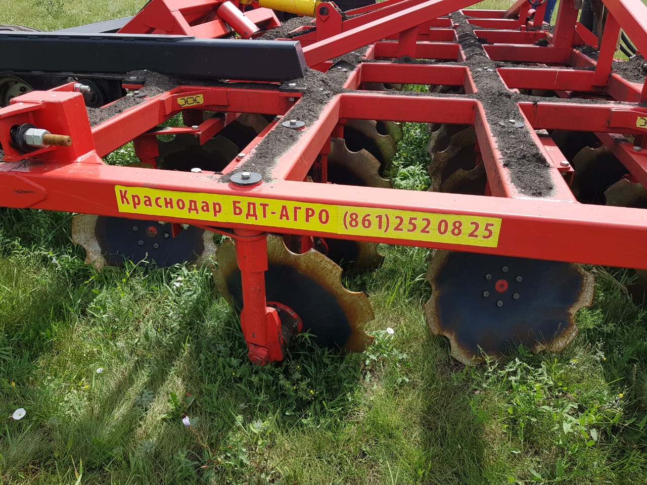
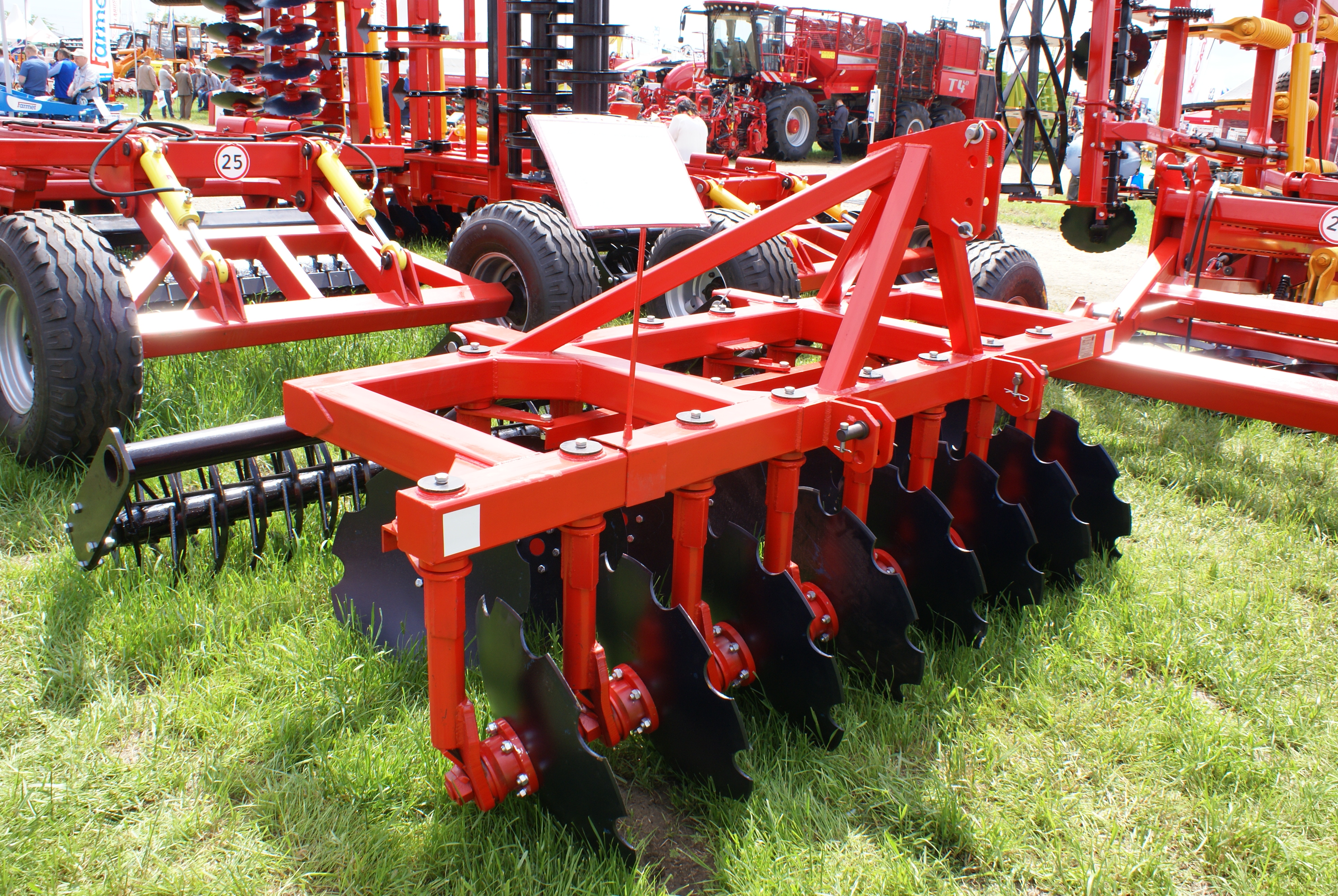
BDM-A is an advanced 4-row disk harrow. The bearing assemblies are installed outside the disk sphere; each disk is attached to a separate tine; the angle of attack is simultaneously adjustable for all disks in a row. It is designed to till the top soil layer up to 17 cm deep, to destroy weed and to chop up crop residues. The disk harrow efficiently operates on soils exposed to wind or water erosion since it uniformly mixes the soil with crop residues. Crop residues uniformly mixed with the top soil layer prevent the soil from being blown or washed away and improve air exchange. Crop residues in the soil are intensively turned into mold improving soil fertility.
The 4-row disc harrow can be used in a wide range of Russian agro-climatic zones and can handle all kinds of soil excluding stony ones. The harrow is an efficient tool for fallow land reuse, preseeding and primary treatment for the min-till approach, renovation of degrading grasslands and grazing areas.


BDM-A 4-Row Harrow Features Compared to 2-Row Harrows:
• 4-row harrows have a relatively large disk-to-disk distance in a row. The disk-to-disk distance in a row is 460 mm, while the row-to-row distance is 675 mm. Therefore, the soil lifted by a row of disks easily passes between the next row disks. So a 4-row harrow can operate in very weed-choked fields and at greater depths.
• The longer frame better absorbs the unevenness of the ground. 4-row harrows are also perfect land planning tools. They easily remove back ridges, backfurrows, deep wheeltracks, moles, etc. A 4-row harrow is your best choice for fallow land reuse.
• All disk tools face a problem: each row of disks tries to pull the harrow in the direction of the disk rotation. The tool turns about the tractor hitch. Since the rows of disks are located at different distances from the hitch, each row applies different loads to the tool. This results in an irregular disk pattern. The rear disks hit the furrows made by the front disks, which leads to poor performance. Each disk tool has its own way of resolving the problem. BRAND NEW! BDT- AGRO launches a new line of 4-row harrows with a new patented disk arrangement. 4-row harrows are perfectly balanced: no imbalance! Neither 2- nor 3-row harrows can be so stable.
Key Advantages of 4-Row Harrows:
1. Originally, 4-row harrows with separate holders for each vertically tilted disk had a disk-to-disk distance of 400 mm within a row. Then this distance was simply divided by the number of rows. So the offset for each holder with respect to the frame came up to just 100 mm. It should be noted that each disk is vertically tilted and its lowermost point almost never matches the holder pivot axis. This resulted in an irregular disk pattern. Many harrow manufacturers still use such an arrangement. Based on the studies performed, BDT-AGRO has developed and tested a new, improved disk layout. The 4-row harrow disk-to-disk distance is 460 mm. For this reason, lower tractor power is required, and up to 12 % of fuel is saved compared to the same-width tools from other manufacturers, while preserving the soil processing quality.
2. All disk tools face a problem: each row of disks tries to pull the harrow in the direction of the disk rotation. The tool turns about the tractor hitch. Since the rows of disks are located at different distances from the hitch, each row applies different loads to the tool. This results in an irregular disk pattern. The rear disks hit the furrows made by the front disks, which leads to poor performance. Each disk tool has its own way of resolving the problem. BRAND NEW! BDT-AGRO launches a new line of 4-row harrows with a new patented disk arrangement. 4-row harrows are perfectly balanced: no imbalance!


3. The tools from BDT-AGRO have disk holders with a grease channel and groove. Lubrication is required just once a season. That is why the harrows have only one grease fitting. In an emergency, you can unscrew the holder mounting bolt, put some grease inside and push it all the way down to the joint while screwing in the bolt. The design significantly improves the joint performance and makes it easier to remove the holder.
4. All the trailed, foldable and mounting tools have a depth adjuster (press wheel) as a standard feature. The wheels installed behind the chassis are adjusted with spring shock absorbers. This significantly reduces loads applied to the tool as it moves over rough terrain or when the tractor pitches and rocks.
5. The new generation bearing assemblies from BDT-AGRO are easier to maintain and much more reliable than the “conventional” design.
6. An optional new generation, maintenance-free cutter can be installed to the standard harrows mounts. In practice, one maintenance-free cutter can treat up to 70 hectares with no user intervention.
7. A common disadvantage of all disk harrows is that the outermost disk in the last row leaves an open, deep furrow. The outmost last row disk holder on the tools from BDT-AGRO is 40 mm shorter than other holders. As a result, the outmost last row disk is positioned 40 mm higher than the other disks. This makes a shallow furrow but still undercuts, grinds and throws enough soil to cover the furrows left by the front row and other rear row disks. The press wheel finishes leveling the field. The patented design of LLC BDT-AGRO tools improves land treatment quality.
8. LLC BDT AGRO provides a 12-months warranty for the frame, the straight holder, the chassis and the drawbar (the warranty does not cover the bearings and wear parts).
Differences between BDM-A Disk Harrows with Bearing Assembly Outside the Disk Sphere and BDM Disk Harrows with Bearing Assembly Inside the Disk Sphere:
1. The main advantage of the design where the bearing assembly is located inside the disk sphere is that this design is widely promoted and commonly used. People are familiar with this type of tool. Of course, if the bearing assembly itself is as large as, for example, the commonly used classic assembly, then yes! The classic elongated bearing assembly is fairly troublesome when it is located outside the disk sphere, especially in 2-row harrows. When the disks within a given row are close to one another, an elongated bearing assembly located outside the disk sphere will lie in the area where soil is discharged from the adjacent disk, which leads to the tool becoming blocked.
Everything is very different when the bearing assembly is relatively compact, like in similar foreign tools. BDT-AGRO’s new-generation bearing assemblies use this approach, where nothing hampers soil discharge from the adjacent disk, even in 2-row harrows.


2. When the bearing assembly is located inside the disk sphere: the labyrinth seal between the rotating flange of the axis and the stationary housing lies in a zone affected by pressure from dust and dirt. As dirt and dust accumulate in the labyrinth seal, they produce wear on the cup or cassette seal, and if gas or dust gets inside the bearing, this can lead to its failure. If this occurs in a serviceable assembly, regular lubrication through the cap can be used to squeeze dirt or dust out. However, it is not possible to affect the dirt pressure and wear process at all when the assembly is non-serviceable or when a cassette seal is used.
When the bearing assembly is located outside the disk sphere: the bearing housing is located behind the disk. There is no dirt pressure. In this case, a non-serviceable bearing assembly with a labyrinth seal will operate for a long time without any problems.
3. When the bearing assembly is located inside the disk sphere: the bearing housing lies within the disk/soil interaction area and will be subject to heavier abrasion. This is especially critical for classic bearing assemblies where the housing is stationary.
When the bearing assembly is located outside the disk sphere: the bearing housing is located behind the disk. There is almost no contact with soil and almost no abrasive wear on the housing.
4 .When the bearing assembly is located inside the disk sphere: high-moisture content and debris causes soil to become clogged between the disk and gang arm. This causes the tool to become blocked and stop working.
When the bearing assembly is located outside the disk sphere: nothing interferes with the working surface of the disk. Such tools have much better terrain handling capabilities when there are high levels of moisture and debris.
5. When the bearing assembly is located inside the disk sphere: When soil impacts on the disk, the axle retaining nut works in tension. The thread is overstressed. This may cause the thread to break, or cause the entire bearing assembly to fail. This is particularly important for classic bearing assemblies.
When the bearing assembly is located outside the disk sphere: when soil impacts on the disk, the load does not affect the axle retaining nut. This makes the design much more reliable.
6 .When the bearing assembly is located outside the disk sphere, the overall working dimensions of the tool increase by about 300 mm. This limits the use of such tools in gardens and vineyards.
7. When the bearing assembly is located outside the disk sphere, the lowest point of the disk is far from the rotation axis of the gang arm. Therefore, changing the attack angle of the disks would theoretically disturb the spacing between the disks on the tool. However, these fears have proved to be unfounded. In practice, the range of attack angle adjustment is small, ±5°, and has no noticeable effect on the spacing.
Advanced BDM –A (with a bearing assembly installed outside the disk sphere) 4-Row Disk Harrows, 2.4 to 8.4 m Wide |
|||||
| Disc harrow description | Modular aggregation | Operating/ tractor width, m | Tractor power, hp | Tractor class | Quantity of disks |
| BDM disc harrows 2,4х4 A | trailed | 2,4\2,6 | 90-100 | 2 | 20 |
| BDM disc harrows 2,8х4 A | trailed | 2,8\3,0 | 100-130 | 2 | 24 |
| *BDM disc harrows 2,8х4 AN | mounted | 2,8\3,0 | 110-130 | 2 | 24 |
| BDM disc harrows 3х4 A | trailed | 3,3\3,5 | 130-150 | 3 | 28 |
| *BDM disc harrows 3х4 AN | mounted | 3,3\3,5 | 130-150 | 3 | 28 |
| BDM disc harrows 3,6х4 A | trailed | 3,6\3,8 | 150-180 | 3 | 32 |
| BDM disc harrows 4х4 A | trailed | 4,2\4,4 | 180-200 | 3-4 | 36 |
| *BDM disc harrows 4х4 AN | mounted | 4,2\4,4 | 180-200 | 4 | 36 |
| BDM disc harrows 5х4 A | trailed | 5,1\5,3 | 220-240 | 4-5 | 44 |
| *BDM disc harrows 5х4 AS | trailed foldable | 5,1\3,0 | 220-240 | 4-5 | 44 |
| *BDM disc harrows 5,6х4 AS | trailed foldable | 5,6\4,1 | 230-250 | 4-5 | 48 |
| BDM disc harrows 6х4 A | trailed | 6,0\6,3 | 250-270 | 5 | 52 |
| *BDM disc harrows 6,5х4 AS | trailed foldable | 6,5\4,1 | 260-300 | 5 | 56 |
| *BDM disc harrows 7х4 AS | trailed foldable | 7,4\4,1 | 310-340 | 5-6 | 64 |
| *BDM disc harrows 8х4 AS | trailed foldable | 8,4\4,1 | 360-400 | 6 | 72 |
| * The depth adjuster is standard equipment. It is optional for other models. | |||||
Advanced BDM –A (with a bearing assembly installed outside the disk sphere) 2-Row Disk Harrows, 1.2 to 8.1 m Wide
BDM-A is an advanced 2-row disk harrow. The bearing assemblies are installed outside the disk sphere; each disk is attached to a separate tine; the angle of attack is simultaneously adjustable for all disks in a row. It is designed to till the top soil layer up to 15 cm deep, to destroy weed and to chop up crop residues. The disk harrow efficiently operates on soils exposed to wind or water erosion since it uniformly mixes the soil with crop residues. Crop residues uniformly mixed with the top soil layer prevent the soil from being blown or washed away and improve air exchange. Crop residues in the soil are intensively turned into mold improving soil fertility.
The 2-row disc harrow can be used in a wide range of Russian agro-climatic zones and can handle all kinds of soil excluding stony ones.
The Main Advantages of the BDM-A Double Harrow Compared to 4-Row Harrows:
• The double harrows have a smaller disk-to-disk distance in a row — 300 mm, while the row-to-row distance is 1,000 mm. The double harrow disks only partially overlap each other. The gaps between the disks are also tilled since the second row disk removes soil and shifts it into the backfurrow made by the first row disk. This does not always happen. However, a second pass diagonally to the first one results in perfect field tilling: the gaps left after the first pass are sliced, and the ridges are removed. As the double harrows have the same number of disks, but are wider, productivity is higher and fuel consumption per area is lower.
• Double harrows are much shorter. They are easier to steer and have a smaller turn radius. For the same reason many double harrows are mounted tools: they apply lower loads to the tractor linkage. Mounted double harrows are significantly cheaper, simpler and easier to steer compared to trailed ones.
• Due to the shorter disk-to-disk distance in a row, double harrows are not as good at negotiating foul and wet fields as 4-row tools. However, for this very reason double harrows make smaller ridges. It is better to use double harrows for smaller ridges, regular tilling of low-foal fields and for preseeding operations.
• BDM is extremely versatile thanks to its adjustable angle of attack. As the angle of attack increases, you can till the land at a relatively low speed, sufficient depths and with no gaps. At a smaller angle of attack and higher speeds you can till the land at a small depth in two passes for subsequent seeding.


Key Advantages of Double Harrows:
1. Based on the studies performed, BDT-AGRO has developed and multiply tested a new, improved disk layout. The BDM double harrow disk-to-disk distance is 300 mm compared to 270 mm for tools from other manufacturers. For this reason, lower tractor power is required and up to 12 % of fuel is saved compared to same-width tools from other manufacturers while preserving the soil processing quality.
2. The tools from BDT-AGRO have disk holders with a grease channel and groove. Lubrication is required just once a season. That is why the harrows have only one grease fitting. In an emergency, you can unscrew the holder mounting bolt, put some grease inside and push it all the way down to the joint while screwing in the bolt. The design significantly improves the joint performance and makes it easier to remove the holder.
3. All the trailed, folded and mounting tools have a depth adjuster (press wheel) as a standard feature. The wheels installed behind the chassis are adjusted with spring shock absorbers. This significantly reduces loads applied to the tool as it moves over rough terrain or when the tractor pitches and rocks.
4. The new generation bearing assemblies from BDT-AGRO are easier to maintain and much more reliable than the “conventional” design.
5. An optional new generation, maintenance-free cutter can be installed to the standard harrows mounts. In practice, one maintenance-free cutter can treat up to 70 hectares with no user intervention.
6. A common disadvantage of all disk harrows is that the outermost disk in the last row leaves an open, deep furrow. The outmost last row disk holder on the tools from BDT- AGRO is 40 mm shorter than other holders. As a result, the outmost last row disk is positioned 40 mm higher than the other disks. This makes a shallow furrow but still undercuts, grinds and throws enough soil to cover the furrows left by the front row and other rear row disks. The press wheel finishes leveling the field. The patented design of LLC BDT-AGRO tools improves land treatment quality.
7. LLC BDT-AGRO provides a 12-months warranty for the frame, the straight holder, the chassis and the drawbar (the warranty does not cover the bearings and wear parts).
Differences between BDM-A Disk Harrows with Bearing Assembly Outside the Disk Sphere and BDM Disk Harrows with Bearing Assembly Inside the Disk Sphere:
1.The main advantage of the design where the bearing assembly is located inside the disk sphere is that this design is widely promoted and commonly used. People are familiar with this type of tool. Of course, if the bearing assembly itself is as large as, for example, the commonly used classic assembly, then yes! The classic elongated bearing assembly is fairly troublesome when it is located outside the disk sphere, especially in 2-row harrows. When the disks within a given row are close to one another, an elongated bearing assembly located outside the disk sphere will lie in the area where soil is discharged from the adjacent disk, which leads to the tool becoming blocked.
Everything is very different when the bearing assembly is relatively compact, like in similar foreign tools. BDT-AGRO’s new-generation bearing assemblies use this approach, where nothing hampers soil discharge from the adjacent disk, even in 2-row harrows.
2. When the bearing assembly is located inside the disk sphere: the labyrinth seal between the rotating flange of the axis and the stationary housing lies in a zone affected by pressure from dust and dirt. As dirt and dust accumulate in the labyrinth seal, they produce wear on the cup or cassette seal, and if gas or dust gets inside the bearing, this can lead to its failure. If this occurs in a serviceable assembly, regular lubrication through the cap can be used to squeeze dirt or dust out. However, it is not possible to affect the dirt pressure and wear process at all when the assembly is non-serviceable or when a cassette seal is used.
When the bearing assembly is located outside the disk sphere: the bearing housing is located behind the disk. There is no dirt pressure. In this case, a non-serviceable bearing assembly with a labyrinth seal will operate for a long time without any problems.
3. When the bearing assembly is located inside the disk sphere: the bearing housing lies within the disk/soil interaction area and will be subject to heavier abrasion. This is especially critical for classic bearing assemblies where the housing is stationary.
When the bearing assembly is located outside the disk sphere: the bearing housing is located behind the disk. There is almost no contact with soil and almost no abrasive wear on the housing.
4. When the bearing assembly is located inside the disk sphere: high-moisture content and debris causes soil to become clogged between the disk and gang arm. This causes the tool to become blocked and stop working.
When the bearing assembly is located outside the disk sphere: nothing interferes with the working surface of the disk. Such tools have much better terrain handling capabilities when there are high levels of moisture and debris.
5. When the bearing assembly is located inside the disk sphere: When soil impacts on the disk, the axle retaining nut works in tension. The thread is overstressed. This may cause the thread to break, or cause the entire bearing assembly to fail. This is particularly important for classic bearing assemblies.
When the bearing assembly is located outside the disk sphere: when soil impacts on the disk, the load does not affect the axle retaining nut. This makes the design much more reliable.
6. When the bearing assembly is located outside the disk sphere, the overall working dimensions of the tool increase by about 300 mm. This limits the use of such tools in gardens and vineyards.
7. When the bearing assembly is located outside the disk sphere, the lowest point of the disk is far from the rotation axis of the gang arm. Therefore, changing the attack angle of the disks would theoretically disturb the spacing between the disks on the tool. However, these fears have proved to be unfounded. In practice, the range of attack angle adjustment is small, ±5°, and has no noticeable effect on the spacing.
Advanced BDM –A (with a bearing assembly installed outside the disk sphere) 2-Row Disk Harrows, 2.4 to 8.4 m Wide |
|||||
| Disc harrow description | Modular aggregation | Operating/ tractor width, m | Tractor power, hp | Tractor class | Quantity of disks |
| *BDM disc harrows 1,2х2 AN | mounted | 1,2\1,3 | 25 | 0,4 | 8 |
| *BDM disc harrows 1,5х2 AN | mounted | 1,5\1,7 | 30-50 | 0,4-0,9 | 10 |
| *BDM disc harrows 1,8х2 AN | mounted | 1,8\2,0 | 50-60 | 0,9 | 12 |
| *BDM disc harrows 2,1х2 AN | mounted | 2,1\2,3 | 60-80 | 1,4 | 14 |
| *BDM disc harrows 2,3х2 AN | mounted | 2,3\2,5 | 70-80 | 1,4 | 15 |
| *BDM disc harrows 2,4х2 AN | mounted | 2,4\2,6 | 80 | 1,4 | 16 |
| *BDM disc harrows 2,6х2 AN | mounted | 2,6\2,8 | 80-90 | 1,4-2 | 17 |
| *BDM disc harrows 2,7х2 AN | mounted | 2,7\2,9 | 80-90 | 1,4-2 | 18 |
| BDM disc harrows 2,7х2 А | trailed | 2,7\2,9 | 80-100 | 1,4-2 | 18 |
| *BDM disc harrows 3х2 AN | mounted | 3,0\3,2 | 100-120 | 2 | 20 |
| BDM disc harrows 3х2 А | trailed | 3,0\3,2 | 100-120 | 2 | 20 |
| *BDM disc harrows 3,3х2 ANS | mounted foldable | 3,3\2,5 | 100-120 | 2 | 22 |
| BDM disc harrows 3,3х2 А | trailed | 3,3\3,5 | 100-120 | 2 | 22 |
| *BDM disc harrows 4х2 AN | mounted | 3,9\4,1 | 130-150 | 3 | 26 |
| *BDM disc harrows 4х2 ANS | mounted foldable | 3,9\2,5 | 130-150 | 3 | 26 |
| BDM disc harrows 4х2 А | trailed | 3,9\4,1 | 130-150 | 3 | 26 |
| *BDM disc harrows 4,5х2 AN | mounted | 4,5\4,7 | 130-150 | 3 | 30 |
| *BDM disc harrows 4,5х2 ANS | mounted foldable | 4,5\2,5 | 140-160 | 3 | 30 |
| BDM disc harrows 4,5х2 А | trailed | 4,5\4,7 | 140-160 | 3-4 | 30 |
| *BDM disc harrows 5х2 AN | mounted | 5,1\5,3 | 150-170 | 3-4 | 34 |
| *BDM disc harrows 5х2 ANS | mounted foldable | 5,1\2,5 | 150-170 | 3-4 | 34 |
| BDM disc harrows 5х2 А | trailed | 4,8\5,0 | 150-170 | 3-4 | 32 |
| *BDM disc harrows 5х2 АS | trailed foldable | 5,1\3,8 | 150-170 | 3-4 | 34 |
| *BDM disc harrows 5,6х2 AN | mounted | 5,6\5,8 | 170-190 | 3-4 | 38 |
| *BDM disc harrows 5,6х2 ANS | mounted foldable | 5,6\2,5 | 170-190 | 3-4 | 38 |
| *BDM disc harrows 5,6х2 АS | trailed foldable | 5,6\3,8 | 170-190 | 3-4 | 38 |
| BDM disc harrows 6х2 А | trailed | 6,0\6,2 | 190-210 | 4 | 40 |
| *BDM disc harrows 6х2 AN | mounted | 6,3\6,5 | 190-210 | 4 | 42 |
| *BDM disc harrows 6х2 ANS | mounted foldable | 6,3\4,4 | 190-210 | 4 | 42 |
| *BDM disc harrows 6х2 S | trailed foldable | 6,3\4,4 | 190-210 | 4 | 42 |
| *BDM disc harrows 7х2 ANS | mounted foldable | 6,9\4,4 | 230-250 | 5 | 46 |
| *BDM disc harrows 7х2 АS | trailed foldable | 6,9\4,4 | 230-250 | 5 | 46 |
| *BDM disc harrows 8х2 АS | trailed foldable | 8,1\4,4 | 250-270 | 5 | 54 |
| * The depth adjuster is standard equipment. It is optional for other models. | |||||